Difference between revisions of "EGR 224/Active Filter"
Jump to navigation
Jump to search
| Line 7: | Line 7: | ||
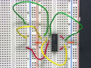
[[Image:TwoBufferAndCopies.jpg|thumb|Closeup of the LM 342 with buffer wiring and OpAmp 1 copy wiring]] | [[Image:TwoBufferAndCopies.jpg|thumb|Closeup of the LM 342 with buffer wiring and OpAmp 1 copy wiring]] | ||
[[Image:TwoBufferAndCopiesAndMeasurements.jpg|thumb|Closeup of the LM 342 with buffer wiring and OpAmp 1 copy wiring; includes four measurement wires (dark green) - reference voltages for these wires in the top blue row and connected to ground]] | [[Image:TwoBufferAndCopiesAndMeasurements.jpg|thumb|Closeup of the LM 342 with buffer wiring and OpAmp 1 copy wiring; includes four measurement wires (dark green) - reference voltages for these wires in the top blue row and connected to ground]] | ||
| + | |||
| + | <br clear=all> | ||
=== Oscilloscope === | === Oscilloscope === | ||
[[Image:ActiveFilterScope.PNG|thumb|Oscilloscope showing four measurement channels with Channel 0 measuring a signal with an approximate maximum amplitude of 1 V]] | [[Image:ActiveFilterScope.PNG|thumb|Oscilloscope showing four measurement channels with Channel 0 measuring a signal with an approximate maximum amplitude of 1 V]] | ||
Revision as of 17:03, 7 April 2009
The following page provides some supplemental information for the Active Filters lab for EGR 119L. It has been updated to Spring, 2009.
Points of Clarification
- 8.4.2 - be sure to complete the wiring in Tables 5.1-5.4 EXCEPT for the wires that go into DAC0OUT, DAC1OUT, and AOGND. Repeat - do NOT install the red wires for DAC0OUT, DAC1OUT, or AOGND. If you are using more than one red wire, you have done something wrong! Installing these wires will short out your audio source and you will not be able to get sufficient volume.
Images
Wiring
Oscilloscope
Click on the pictures at right to make them larger.


