EGR 224/Circuit Building and Measurements
$$ \newcommand{\E}[2]{#1_{\mathrm{#2}}} $$ This page will contain some tips and pictures for the EGR 224 Labs on Circuit Building and Measurements. It has been updated for Spring 2023.
Contents
Introduction
To do this lab you will need to understand how to use the following:
- Resistor Color Codes for determining nominal resistor values and tolerances,
- How breadboards work and specifically how the PBB 272 powered breadboard (hereafter, PBB) works, and
- How multimeters work and specifically how the MS8264 multimeter works.
Inventory
Your group will need to have a powered breadboard - this should already be there; if not, move to a different table. There should red, yellow, and black cables already attached to the V+, V-, and GND posts of the PBB. Be sure the PBB is off.
Your group will also need to get the following from the front of the room:
- A multimeter inside a cardboard box. The box should also have a white cable and a green cable.
- Six resistors - two 1 k$$\Omega$$ (brown-black-red-gold), two 2.2 k$$\Omega$$ (red-red-red-gold), and two 1 M$$\Omega$$ (brown-black-green-gold). These are available in labeled boxes at the front of the room. At the end of lab, be sure to put these back in the right boxes.
- A general supplies box - these are the translucent plastic boxes at the front of the room. Among other things, these should have seven wires - red, yellow, black, green, white, brown or orange, and blue or purple.
When you start the lab, check to make sure you have gathered all the things. Before you leave the lab, make sure a TA checks you off for still having all the things!
Resistance Measurements
Do not hold the resistors when taking resistance measurements - use the alligator clip cables to connect the leads of the resistor to the probes of the multimeter. Make sure the multimeter is set to measure resistance with the smallest usable range in order to get the highest possible precision. On the MS8264, resistance measurements are generally near the top of the dial.
Voltage Divider
Voltage Measurements
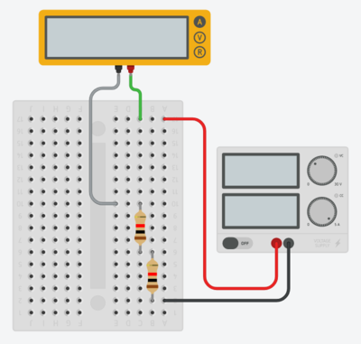
There are three different measurements you need to make. The first will be the total voltage - go by what your multimeter says and not by the digital readout on the powered breadboard. The second will be measuring the voltage drop across the top resistor (A), and the third will be measuring the voltage drop across the bottom resistor (B).
Current Measurement
Schematics
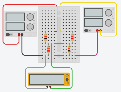
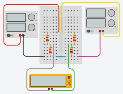
These are Tinkercad representations of how you should build your physical circuits. Your wiring should generally match these.
- The top left resistor is $$\E{R}{1ka}$$ and the bottom left resistor is $$\E{R}{2.2ka}$$.
- The top left source is the positive voltage source from the powered breadboard (PBB) - the black wire is the ground wire and the red wire is the positive voltage wire. The top right source represents the negative voltage source from the PBB and the yellow wire represents that negative voltage. The pink wire will not actually physically exist on your circuit; both the positive and negative sources on the PBB are connected to the same ground, but Tinkercad actually needs two separate connections.
- The brown wire in the top picture may be orange for you; it is meant to connect the subnode attached to $$\E{R}{1ka}$$ and $$\E{R}{2.2ka}$$ to the subnode attached to $$\E{R}{1kb}$$ and $$\E{R}{2.2kb}$$; it is the wire through which $$\E{i}{y}$$ flows. In the second figure, note that the wire has been replaced by the multimeter in ammeter mode.
- The blue wire in the figure may be purple for you - it is meant to connect the ground of the PBB and the bottom of $$\E{R}{2.2ka}$$ to the bottom of $$\E{R}{1kb}$$; the negative voltage source is internally connected to the same ground as the positive voltage source (which is why the pink wire in the drawing will not show up in your circuit).
Voltage Measurement
Current Measurement
Lab Report Clarifications
Here are some clarifications on what should be included in the lab report:
- Resistance Measurements:
- For Color Bands, you can put the names of the colors (brown-black-red-gold)
- For Nominal Tolerance, they were all 5% (gold for the fourth band); if your table gets too wide because of the color bands, you can shorten the header to Nom. Tol.
- Voltage Divider Voltage Measurements:
- For Calc. Voltage, use the basic voltage divider equation with your actual measured resistors
- For Sim. Voltage, use your Tinkercad voltage divider circuit from Lab 2 and measure the voltage across each resistor - just change the resistor values to what you measured in the lab.
- The color bands in Tinkercad will be based on a rounded version of your resistors but the measurements will be based on the full value. You do not need to include the Tinkercad schematic in your lab report, just the results of putting your values in.
- You should only have one multimeter in your Tinkercad circuit, and you will need to move the probes to check the top resistor and then the bottom resistor. If you try to take both measurements at once, you are not accurately simulating the process used in the lab.
- Voltage Divider Current Measurements:
- For Calc. Current, use Ohm's Law with your actual measured resistors
- For Sim. Current, use your Tinkercad voltage divider circuit from Lab 2 and measure the current through the network - just change the resistor values to what you measured in lab. Once again, you should only have one multimeter in your Tinkercad circuit (this time in series with the resistors).
- Yours To Build:
- Use your measured resistor values in each case.
- The Tinkercad version will have two multimeters - one voltmeter to measure $$\E{v}{x}$$ and one ammeter to measure $$\E{i}{y}$$.
- The MultiSim version will have a single V/A probe to measure both $$\E{v}{x}$$ and $$\E{i}{y}$$.


