Python:DAQ 2 Virtual
This page contains pictures and graphs related to DAQ 2 for EGR 103. It has been updated for Spring 2020 to be virtual.
Contents
Introduction
The goals for this lab include learning how to set and measure analog voltages and learning a little more about how LEDs work. Given that the lab will now be virtual, there will be pictures and other schematics here and you will get data sets to use.
Circuits
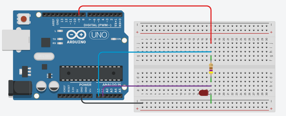
For this experiment, you will be applying a voltage to a series combination of a resistor and a diode. The voltage will be divided between the two elements. To keep track of the individual voltages, we will measure the total voltage and the voltage at the connection between the resistor and the LED. With those two measurements we can calculate three different voltages:
- The total voltage, given by the total voltage measurement (blue wire),
- The LED voltage, given the the voltage measurement of the middle node (purple wire), and
- The resistor voltage, given by the difference between the total voltage measurement and the LED voltage.
Quick note Though an Arduino is shown here, the data sets you will have were generated via a different simulation mechanism. The Arduino UNO is not capable of setting true analog voltages but rather simulates different levels through something called "pulse width modulation." The outputs can only by either 0 V or 5 V, but if you want to simulate a value in between, the pin rapidly switches between 0 and 5 V. The pin will be "on" for the same proportion of a period as the voltage you want to simulate divided by 5 V. For instance, if you want to simulate 4 V, the pin would be on 80% of the time. There are many applications where this works perfectly fine; this just happens to be not one of them...
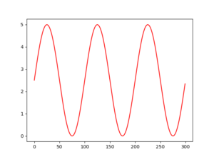
Graph from aio_meas1
Graph showing single measurement when the overall voltage is calculated with:
v_out = 2.5 + 2.5 * np.sin(6 * np.pi * k / N)
That is,
\( \begin{align} V_{out}=2.5+2.5\sin\left(\frac{6\pi k}{N}\right) \end{align} \)
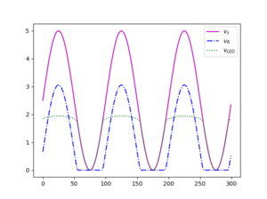
Graph from aio_meas3
Graph showing all three measurements when the overall voltage is calculated with:
v_out = 2.5 + 2.5 * np.sin(6 * np.pi * k / N)
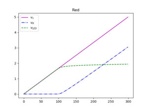
Graph from aio_get_data
Graph showing all three measurements when the overall voltage is calculated with:
v_out = 5 * (k / (N - 1))
assuming N = 300. Note at the far left that they all start at either exactly 0 V!
Codes
Here are the codes references in the assignment. Note that the extra blank spaces are in earlier programs to make room for the code added to later programs. For the second and later codes, the lines that were added or changed from the script listed immediately above it will be indicated with yellow highlighting.
 1 # %% Import modules
 2 import numpy as np
 3 import time
 4 import nidaqmx as daq
 5
 6
 7 # %% Create a task
 8 taskout = daq.Task()
 9
10
11 # %% Add analog output lines
12 taskout.ao_channels.add_ao_voltage_chan("Dev1/ao0")
13
14
15
16
17 # %% Check lights
18 taskout.write(5)
19 input("PAUSED - Hit return to continue ")
20 taskout.write(0)
21
22 # %% Write values to output
23 N = 300
24
25 for k in range(300):
26     v_out = 2.5 + 2.5 * np.sin(6 * np.pi * k / N)
27     taskout.write(v_out)
28     time.sleep(0.01)
29
30
31 # %% Turn all off when finished and close task
32 taskout.write(0)
33 taskout.close()
 1 # %% Import modules
 2 import numpy as np
 3 import time
 4 import nidaqmx as daq
 5 import matplotlib.pyplot as plt
 6
 7 # %% Create a task
 8 taskout = daq.Task()
 9 taskin = daq.Task()
10
11 # %% Add analog output lines
12 taskout.ao_channels.add_ao_voltage_chan("Dev1/ao0")
13
14 # %% Add analog input lines
15 taskin.ai_channels.add_ai_voltage_chan("Dev1/ai0")
16
17 # %% Check lights
18 taskout.write(5)
19 input("PAUSED - Hit return to continue ")
20 taskout.write(0)
21
22 # %% Write and read values
23 N = 300
24 meas = np.zeros((N, 1))
25
26 for k in range(N):
27     v_out = 2.5 + 2.5 * np.sin(6 * np.pi * k / N)
28     taskout.write(v_out)
29     time.sleep(0.01)
30     meas[k] = taskin.read()
31
32 # %% Turn all off when finished and close task
33 taskout.write(0)
34 taskout.close()
35 taskin.close()
36
37 # %% Make plots
38 fig, ax = plt.subplots(num=1, clear=True)
39 total = meas[:, 0]
40 ax.plot(total, "r")
 1 # %% Import modules
 2 import numpy as np
 3 import time
 4 import nidaqmx as daq
 5 import matplotlib.pyplot as plt
 6
 7 # %% Create a task
 8 taskout = daq.Task()
 9 taskin = daq.Task()
10
11 # %% Add analog output lines
12 taskout.ao_channels.add_ao_voltage_chan("Dev1/ao0")
13
14 # %% Add analog input lines
15 taskin.ai_channels.add_ai_voltage_chan("Dev1/ai0:2")
16
17 # %% Check lights
18 taskout.write(5)
19 input("PAUSED - Hit return to continue ")
20 taskout.write(0)
21
22 # %% Write and read values
23 N = 300
24 meas = np.zeros((N, 3))
25
26 for k in range(N):
27     v_out = 2.5 + 2.5 * np.sin(6 * np.pi * k / N)
28     taskout.write(v_out)
29     time.sleep(0.01)
30     meas[k, :] = taskin.read()
31
32 # %% Turn all off when finished and close task
33 taskout.write(0)
34 taskout.close()
35 taskin.close()
36
37 # %% Make plots
38 fig, ax = plt.subplots(num=1, clear=True)
39 total = meas[:, 0]
40 resv = meas[:, 1]
41 ledv = meas[:, 2]
42 ax.plot(total, "m-", resv, "b-.", ledv, "g:")
43 ax.legend(["$v_s$", "$v_R$", "$v_{LED}$"])
 1 # %% Import modules
 2 import numpy as np
 3 import time
 4 import nidaqmx as daq
 5 import matplotlib.pyplot as plt
 6
 7 # %% Create a task
 8 taskout = daq.Task()
 9 taskin = daq.Task()
10
11 # %% Add analog output lines
12 taskout.ao_channels.add_ao_voltage_chan("Dev1/ao0")
13
14 # %% Add analog input lines
15 taskin.ai_channels.add_ai_voltage_chan("Dev1/ai0:2")
16
17 # %% Check lights
18 taskout.write(5)
19 input("PAUSED - Hit return to continue ")
20 taskout.write(0)
21
22 # %% Write and read values
23 N = 300
24 meas = np.zeros((N, 3))
25
26 for k in range(N):
27     v_out = 5 * (k / (N - 1))
28     taskout.write(v_out)
29     time.sleep(0.01)
30     meas[k, :] = taskin.read()
31
32 # %% Turn all off when finished and close task
33 taskout.write(0)
34 taskout.close()
35 taskin.close()
36
37 # %% Make plots
38 fig, ax = plt.subplots(num=1, clear=True)
39 total = meas[:, 0]
40 resv = meas[:, 1]
41 ledv = meas[:, 2]
42 ax.plot(total, "m-", resv, "b-.", ledv, "g--")
43 ax.legend(["$v_s$", "$v_R$", "$v_{LED}$"])
44
45 # %% Save values and figure
46 color = input("Color: ")
47 eval("ax.set_title('{:s}')".format(color))
48 fid = eval("open('{:s}_data.dat', 'w')".format(color))
49 for k in range(300):
50     fid.write("{:.4e} {:.4e} {:.4e}\n".format(*meas[k, :]))
51 fid.close()
52 eval("fig.savefig('{:s}_plot.png')".format(color))
Questions
Post your questions by editing the discussion page of this article. Edit the page, then scroll to the bottom and add a question by putting in the characters *{{Q}}, followed by your question and finally your signature (with four tildes, i.e. ~~~~). Using the {{Q}} will automatically put the page in the category of pages with questions - other editors hoping to help out can then go to that category page to see where the questions are. See the page for Template:Q for details and examples.


